When it comes to towing a vehicle behind your RV, whether it’s a small car, SUV, truck, or trailer, there’s some lighting required there to make sure it can be seen, and that your intentions–namely turning and braking–are effectively communicated. With the exception of trailers, you’re generally taking a vehicle who’s manufacturer didn’t really design things to make setting that up easy, and most “professional” installers make use of one of a few tactics (that aren’t legal) to make their job as repetitive as possible.
This page is going to lay out what’s required first, as it applies to towing a vehicle that’s normally self-propelled. We’re going to assume that the vehicle has all of the equipment required by law for when it’s operating on its own, and that it’s working properly in that regard. We’re going to leave out some special cases for really small trailers, really large vehicles (over 30′ long), and FMCSA regulations that would apply in commercial service. We’re also going to stick to what’s in FMVSS 108, which applies in all 50 states. States can have additional requirements (flares in RVs are an example), and they can also prohibit certain equipment that federal law permits.
Required Equipment
- Reflex reflectors, on the sides front and rear, and on the rear facing rearward. These are the amber (front) and red (rear) reflectors with a small triangular pattern that reflect light back in the direction it came from. Unlike a simple mirror or the shiny surface inside any of your lights, this means that light goes back toward another vehicle, so they can see your vehicle from a much greater distance, particularly when parked, disabled, or if a wiring malfunction occurs and you haven’t noticed yet. If the vehicle was legal on its own, it already has reflectors meeting these requirements. Since they’re passive, we don’t need to worry about them further.
- Stop, tail, and turn signal lamps. These generally get the most attention, as they’re the lights that are the most “active” and garner the most attention. We’ll talk about them more later, but most already understand their importance and function.
- License plate lamp. Not so much for avoiding an accident, but it does help in identifying your vehicle. Yes, this is required.
- Side marker lights. On the sides of the vehicle, at front (amber) and rear (red). These may be integrated with other light bulbs/fixtures as your car was manufactured. Their primary function is to make the vehicle’s presence and length visible.
What do I need to get started?
- Wiring diagrams. There are a number of places to find these for free, from online forums to the repair guides from AutoZone. If you don’t find the diagrams for your car, the best (albeit $27) resource is AllData DIY. That will get you access to all of the factory repair information (the same stuff the dealer will have) for your year, make, and model of vehicle. A few minutes with the wiring diagrams can save you hours of probing around, running wires, etc., and leave you with a much cleaner installation. Often, you’ll be able to make all the connections needed right at the front of the car.
- Plug for connecting to tow bar/RV. I prefer using the combination of this plug and harness. The connection at the back of the plug is a MetriPack connection, with weather seal. Instead of screw terminals in a rough environment, the harness length lets you get into the engine bay to make your field connections. Not to mention, pretty inexpensive. If you ever break the plug itself, it’s a quick job to replace.
- Connectors. Depending on where and how, and what you prefer, anything from OE-style connectors where you make a plug-in adapter, solder and heat shrink, butt splices or quick splices. Advantages and disadvantages for all of them; figure out where you’re going to make connections before deciding.
- 4-wire to 5-wire converter. If your vehicle has separate brake and turn signal lights on the rear, you’ll need one of these to break out the combined signal that’s on the 7-wire plug on your motorhome. It’ll cost a few bucks more ($25 as of writing), but you gain the advantage of being able to check your lights from the RV’s driver’s seat using your rearview camera.
- Hook-up Wire. Since your car’s factory wiring will often make use of wires with stripes or dots, which you won’t find at the local parts store, stick to the color coding on the trailer plug. White, brown, yellow, and green for the lights. Wire size isn’t as important as the quality of the connections. Your car’s wiring will likely be significantly smaller than the wiring on the trailer plug, so pick a size in between ease connecting them together–typically something in the 16 to 18 AWG range.
- Tools. Voltmeter, wire cutters and strippers, crimpers, and possibly screwdrivers or other tools for gaining access to wiring.
Notice what’s not on the list: diodes, spade connectors, bulbs, bulb sockets, or drill bits. You don’t need any of them, and if someone suggests using them, following their method will likely leave you with a setup that doesn’t meet the lighting requirements in FMVSS. Why that happens, and the rammifications, will be saved for another document.
How do I get started?
Everything starts with the wiring diagrams. The plan here is to gradually introduce guides that simply tell you where to go and what wires to connect to for popular vehicles, but that’s going to take some time. Using the AlldataDIY site, we’ll drill down into finding the wiring diagrams for the parking light circuit on a 2005 Mazda 6s, to give you a feel for how that works (click on images to enlarge).
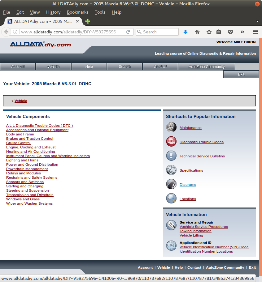


Once we do that, we’ll get a diagram showing the component of interest, generally spread over several images. The ease of use depends on the vehicle manufacturer–American makes are generally the easiest to follow, and Smart has to be one of the most difficult (more on that later). In most cases, in addition to an electrical schematic, you’ll also get a diagram showing where the harness runs. That’s useful in figuring out the easiest place to make  your connections.
These diagrams are among the easier to follow–power at the top of the page, ground at the bottom. This style makes it easy to follow how the circuits work, but sometimes a little more difficult to identify the point where all the wires we need come together in one spot.
Marker and Tail Lights
When we look at the diagrams above, we can see that the LG/B wire that provides power to the lights on page 3a continues to page 3b and provides power to all of those lights as well. This is a good thing (and very common for marker lights), as it means we can make one connection and light up 10 bulbs! On this particular vehicle, not all would technically be required, but connecting to the LG/B wire will cover the tail lights, license plate light, and all 4 side marker lights (the rear side marker light function is provided by the outboard tail lamp bulb).
Ok, so we’ve found it. Where do we connect? Anywhere we can get at that LG/B wire. Since we’re bringing our 7-pin plug in at the lower front bumper, the front of the car is obviously easiest. The parking light at first seems easiest, as it’s readily visible at the back of the headlight housing as soon as you open the hood. But there’s not much wire to work with. Instead, we can make the connection on the length of wire that heads down toward the front side marker light–that way we have about a foot of exposed wire to work with, and make the connection without worrying about messing something else up. Connect to this wire with brown wire coming from the 7-pin plug.
Turn Signals
Here’s where things start to get just a bit more interesting. The car we’re working with has separate brake and turn signals. How do you know what you have? In this case, it’s a dead giveaway–the turn signals are amber. If you don’t have any amber lights on the back, you’ll have to find a helper to step on the brakes with the turn signals on to see if they’re separate circuits or not.
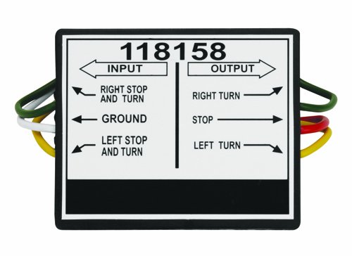
Since we’re dealing with a “separate” system, and the RV (like most) is configured for combined stop and turn lamps, we’ll be using a converter, as shown below. The output side will be connected to the car’s wiring, while the input side will go to the RV plug.
Back to the wiring diagrams for just a bit–locate the turn signal wiring diagram:
Here it becomes obvious that the front and rear signals share an output from the flasher control module. We could trace that diagram to confirm that it’s supplying a connection to the positive side of the circuit, but since we can see ground on this page, we already know that. For the right side, we’ll be connecting to the wire labeled G/W (green with white stripe). This wire is present at the headlight assembly, and we connected our marker lights away from here, so that’s going to be the easiest place to tie in. So take the green wire from the converter output to the right headlight assembly, and the yellow one to the driver’s side. Tie into G/W on the right, and G/D (green with dark blue) on the left. So far so good?
We’re getting closer. The green (right turn) input to the converter should go to the right turn connector on the 7-pin harness (also green), and the yellow (left turn) input should go to the yellow left turn wire on the harness.
Brake Lights
At this point, the converter has two wires not connected–stop and ground. The stop wire needs to connect to the car’s brake lights. The hardest part of this connection is running the wire–it’s the first we’ve encountered on this car that isn’t accessible standing at the front of the car. It’ll need to be fished through a grommet in the firewall, and head toward the brake pedal. If you’re installing a supplemental/breakaway braking system, now’s a good time to run the blue electric brake wire through as well.
Back to the wiring diagrams for just a minute:
Maybe I should have started with the brake lights. This is even simpler than the other functions to read. You can see power leave the battery in the top left corner, through a fuse, and to the brake light switch, mounted on the brake pedal arm, via a G/W wire. Without your foot on the brake, the switch is open and this isn’t connected to anything. To light the brake lights without stepping on the pedal, we need to connect to the G/Y (green with yellow stripe) wire near the switch.
Grounding
Easily overlooked, but more important than any of the other connections as it’s a single point failure for all of your lights. You also can end up with lights dimming in response to other circuits if you don’t have a good ground. Take the white wire from the 7-pin harness and the white wire from the light converter and connect both to a good chassis ground. I recommend against just finding a body screw and instead looking for a factory grounding point.
Testing
If you’ve done everything correct to this point, you should be able to power on each of the relevant light circuits. Turn the RV’s headlights on, use both turn signals, and step on the brake pedal to make sure everything’s functioning. By making connections at these points, we haven’t run any wire further back on the car than about where the driver’s feet would be. We’ve preserved all of the light functions required on a trailer–including powering the center-mount stop lamp which isn’t required for a trailer but helps with visibility.
You need no diodes–you’re not feeding the lights any differently than they would be fed when the car is operating under its own power–and you haven’t modified your light housings in any way. If you have a rear view camera, you can easily see your front turn signals and marker lights come on while operating them from the driver’s seat of the motorhome, making it a single person job and just a tad quicker hitting the road. Turn on the hazard flashers and visually check that the brake lights are working and you’re good to go!
What if my toad’s brake and turn signal functions are combined on the same circuit?
Everything above still applies, except you won’t need the converter box. The green and yellow wires from the 7-pin plug will connect directly to the circuits on your vehicle. That makes the electrical sophistication just a tad simpler, but you’ll likely have to go further toward the back of the vehicle to make the needed connections, as your front turn signals won’t be connected to the lights on the back.